Here are some photos showing the construction of the peg matrix from my School Rhythmer drum machine project:
Basically, it involves micro-switches, wires and diodes arranged in columns and rows, creating an 8 x 5 matrix
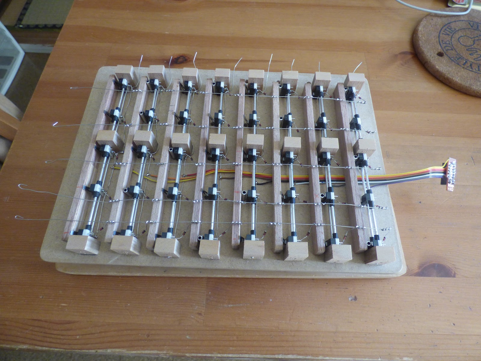
The columns carry the trigger signals from the step sequencer - there are only eight steps - while the rows carry the trigger signals to each of the five drum sounds. When a peg is inserted, it closes the associated micro-switch so that the particular drum sound is triggered at that step.

The diodes isolate each switch from the matrix. Without these, any trigger signal would dissipate throughout the whole matrix triggering every drum sound that has a peg inserted along its row, regardless of the current step.
The rest is 'mechanical'. I used micro-switches as a cost effective solution. An alternative might be 3.5mm jack plugs and sockets, such as the switching type that make/break a circuit when a plug is inserted. A further idea would be to use tact switches whereby inserting a peg keeps the switch depressed. Of course, foregoing the whole peg idea and simply using toggle switches would make everything much easier but this project was intended to capture the 'charm' of the original Kawai machine.
Since the micro-switches are activated by levers, I found it worked best to align them perpendicular to the surface of the matrix (as can hopefully be seen in the photo above). This way, when a peg is inserted, it gently but firmly closes the switch. To achieve this, the switches needed to be aligned correctly behind the holes for the pegs. Fortunately, the micro-switches, having mounting holes through their base, could be slid onto rails (aluminium pipe in this case) and their alignment easily adjusted. Again, the photo above hopefully shows this. Furthermore, some support is needed to keep the pegs straight when inserted since the sprung levers of the micro-switches will push them away. This was achieved quite easily with strips of wood positioned to counter the force of the levers: the pegs are simply held between the lever and wooden strip.

On the face of the peg matrix I used small rivet/eyelets (the kind of thing used in leathercraft) which serve to both support the pegs and enhance the aesthetics. The pegs themselves are short lengths of 3.5mm aluminium pipe with painted wooded handles. Almost any material would be fine since the pegs themselves are not making electrical contact. The important thing here was getting the diameter of the eyelets and pegs right so that they can be inserted and removed smoothly, while remaining firmly in place when inserted.
OK, that's all for now. I'll add more details later if any questions arise.
Wow! Really cool! I'm planning on something like this, i'm a complete beginner, i've seen on your vid that japanese drum kit, that generates the sound of the drum machine, the peg matrix is the sequencer. How does it connect? Would be great to have more pictures from more sides of the build. I'm interested in building my own things too, if this take you too much time i don't mind, if that is the case, would you mind at least saying where should i start and seach for making this level of builds? Thanks!
ReplyDeleteps: Do you plan reviving this blog? I've noticed this was the first post in years.
Thanks for checking this out and apologies for the slow response.
DeleteCurrently, I struggle to find time to post new content here, or anywhere else for that matter. But if anyone asks about my projects, I'll endeavour to follow up as best I can (I made this recent post as someone had asked for details on the peg matrix on YouTube).
Regarding how it connects:
- The sequencer is built around a 4017 IC - it's pretty much the well known Baby 8 sequencer if you're familiar with that.
- Each step of the sequencer is wired to a 'column' of the matrix - so eight steps cycle through the eight columns.
- Each column has five peg sockets wired to five rows which send the sequenced triggers to the five drum sounds.
Obviously, some pictures and some schematics would help explain all this as there's a bit more to the build in terms of getting the sequencer to generate suitable trigger signals.
Most of my build notes are somewhat chaotic and need compiling into something that would make sense to others but if you give me some time, I'll make an updated post with schematics, etc. Others have asked so I should get it done!
In the meantime, feel free to ask any questions of specific details. As a starting point, I'd suggest looking at the Baby 8 sequencer project which is easily found on the Internet. If that looks like something you could build, then it's not a great leap to adapt it to sequencing drums. The drum sounds themselves could be anything that can be triggered by the signals generated by the sequencer - DIY circuits, an existing drum machine or a modified device like a Casiotone keyboard for example.